
Braced Frame Design
- nick8284
- Apr 7
- 3 min read
Introduction
Braced frames are one of the most efficient and widely used lateral force-resisting systems in structural engineering. Their simplicity, strength, and stiffness make them an ideal choice for buildings subject to wind and seismic loads—particularly when cost and constructibility are driving factors. In this post, we’ll walk through the essentials of braced frame design, covering key decisions around geometry, member and connection design, and foundation requirements. We'll also show how CalcBook can streamline your workflow with a clear, code-compliant example problem.
What Are Braced Frames?
Braced frames resist lateral loads primarily through the axial action of diagonal members—braces—which form triangular configurations within the structural frame. When lateral forces act on the structure, these braces carry the loads through tension and compression, reducing demands on the beams and columns compared to moment frames.
Braced frames are commonly used in low- to mid-rise structures, warehouses, industrial buildings, and wherever architectural flexibility is less of a concern. Their key advantages include cost-effectiveness, reduced lateral displacement, and straightforward design. However, their placement can interfere with window openings or interior layouts, requiring early coordination with architectural plans.
Key Considerations
Here are the primary factors to keep in mind when designing a braced frame:
Geometry: The configuration of braces—whether X, V, inverted V, or single diagonal—directly affects the distribution of forces and the frame's behavior. Ensure that brace angles and layout allow for efficient load paths and minimal eccentricity.
Loads: As with any lateral system, consider wind, seismic, and gravity loads in accordance with ASCE 7. Pay special attention to seismic detailing requirements if the frame is designated as an SCBF (Special Concentrically Braced Frame) or OCBF (Ordinary Concentrically Braced Frame).
Material Properties: Evaluate the steel grade and section types to balance strength, stiffness, and availability. Brace members are often slender and must satisfy both strength and stability criteria under axial loading.
Member Design: Braces are primarily axial members, but in seismic applications, ductility and buckling behavior become critical. Beams and columns must also be checked for combined axial and flexural effects, especially where unbalanced brace forces introduce moment.
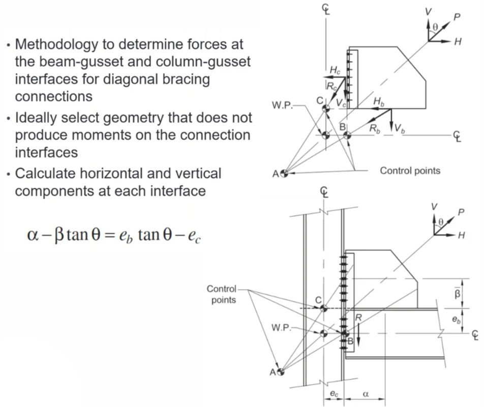
Connection Design: Braced frame connections must transfer significant axial forces and accommodate deformation demands, particularly under seismic loading. The Uniform Force Method is a reliable approach to determine the forces at the beam-gusset and column-gusset interfaces in diagonal brace connections. This method simplifies the force transfer by assuming uniform axial and shear forces at each interface, helping to avoid overcomplicating the analysis. When selecting brace geometry, aim for configurations that minimize or eliminate moments at these interfaces, resulting in a more direct and efficient load path.
Foundation Design: The foundation must resist the vertical and horizontal components of brace forces. Pay particular attention to uplift, especially under seismic load combinations. Spread footings or grade beams may be needed to transfer and balance forces.
Example Problem
The example problem below is divided into three sections: Member Design, Connection Design, and Foundation Design (Solutions Provided Using CalcBook) Part 1: Member Design Problem Statement:
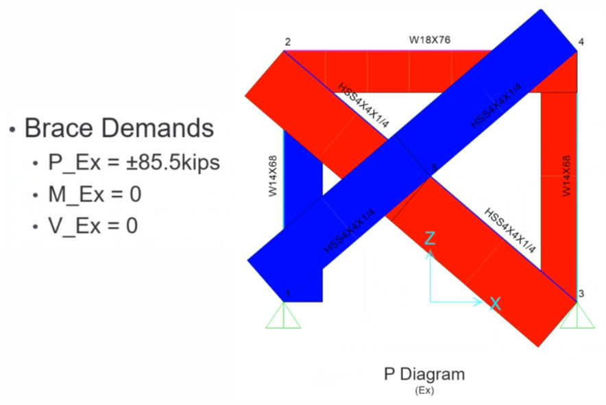
Analysis Results:
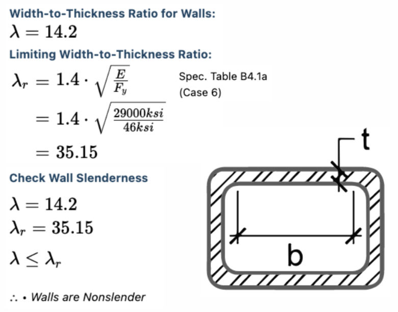
Slender Element Check:
Effective Slenderness Ratio:

Controlling Buckling Stress:
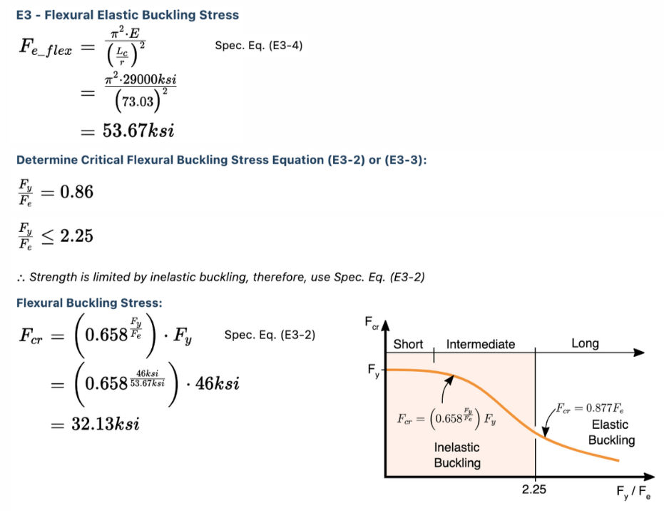
Design Capacity:
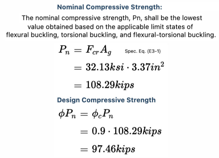
Controlling Demand/Capacity Ratio:

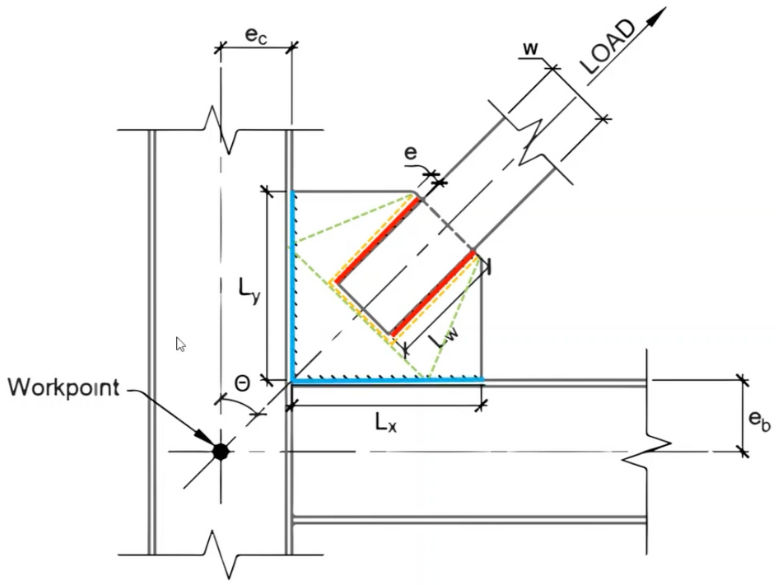
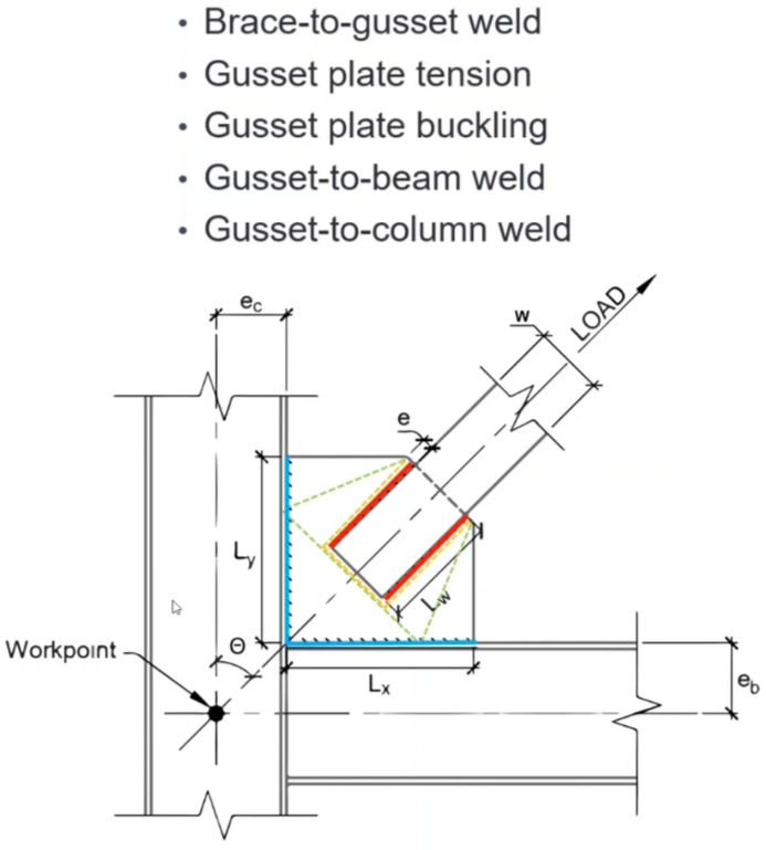
Part 2: Connection Design
Uniform Force Method:
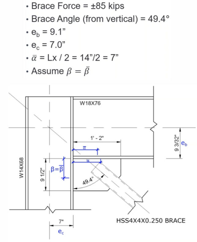
Problem Statement:
Design Checks:
Assumptions:
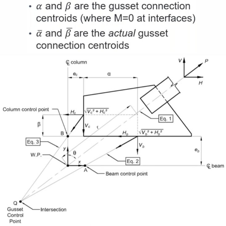
Free Body Diagram:

Brace-to-Gusset Weld:

Buckling of Gusset:

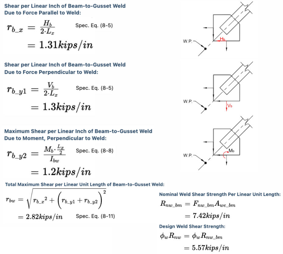
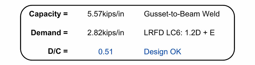
Beam-to-Gusset Weld:
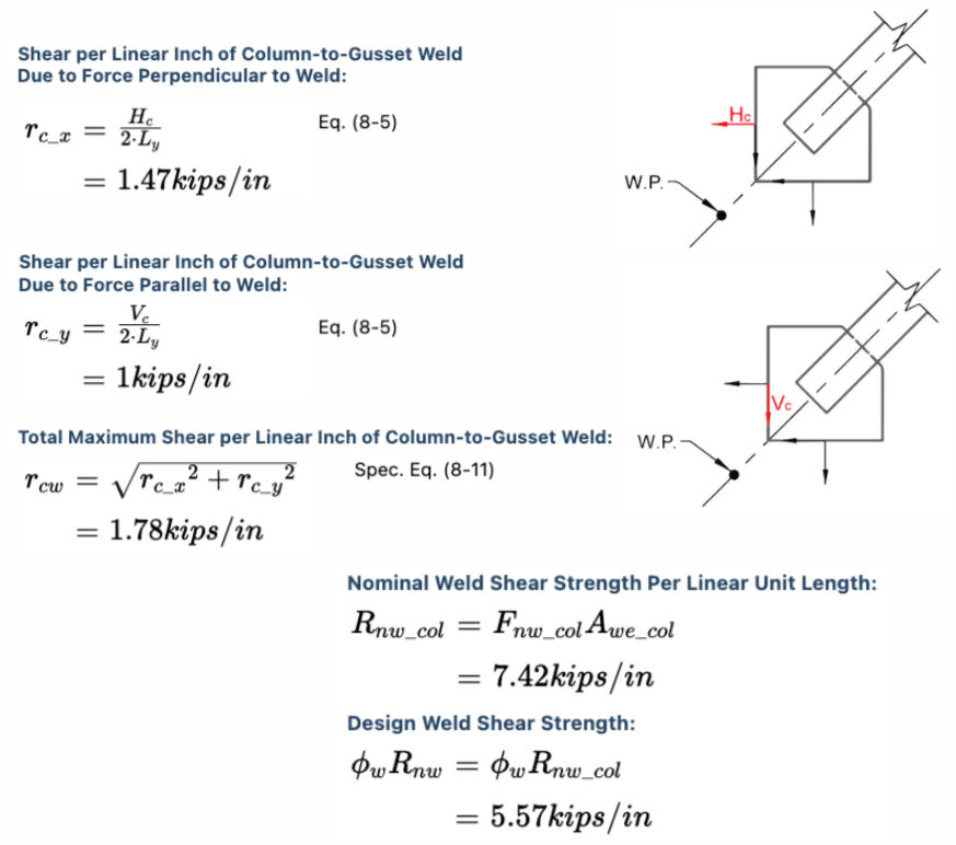
Column-to-Gusset Weld:
Controlling Demand/Capacity Ratio:
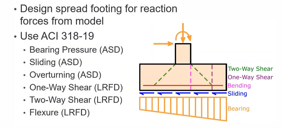
Part 3: Foundation Design
Problem Statement:
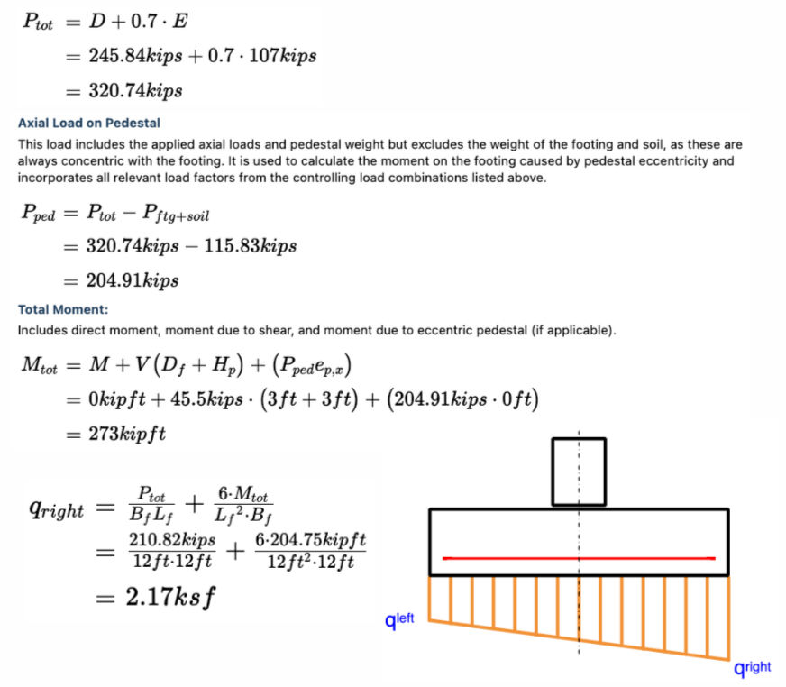
Design Loads:

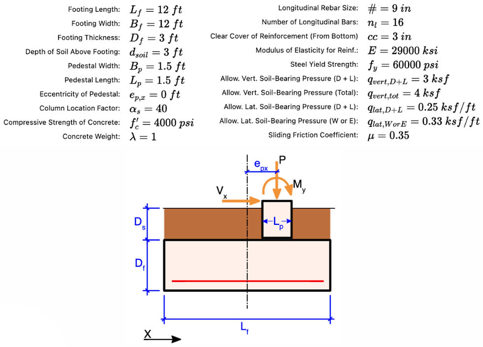
Input Summary:
Bearing Pressure:
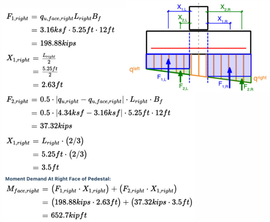
Bending Demand:
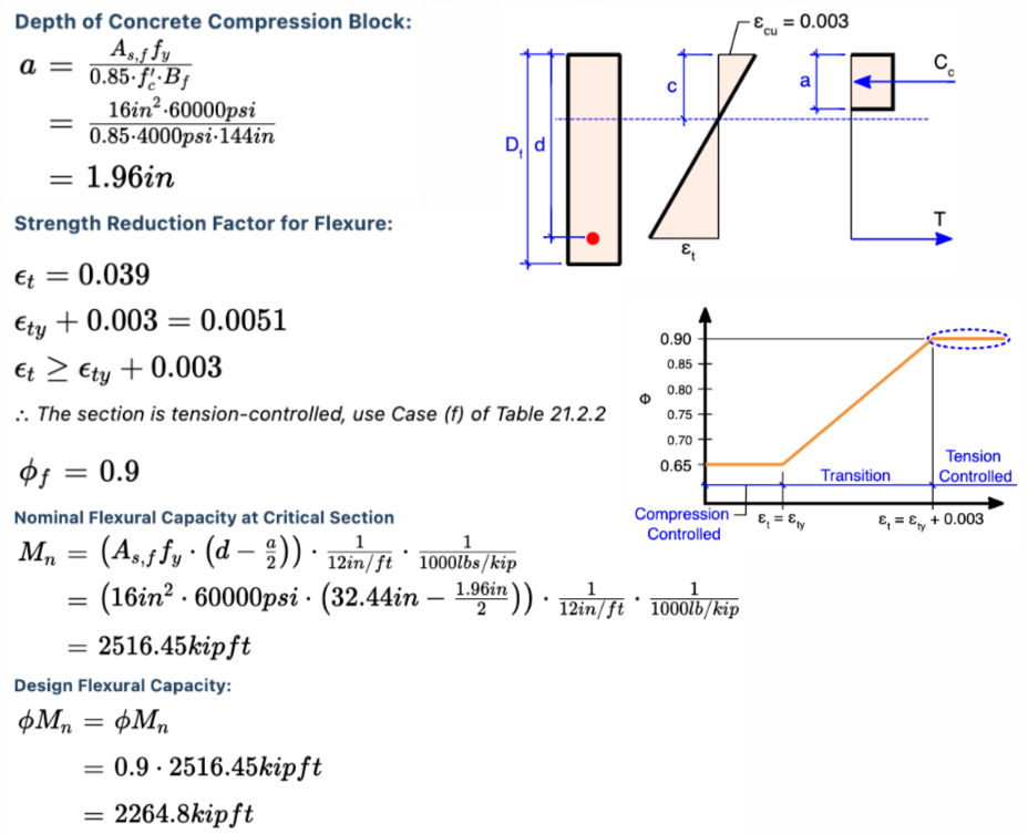
Bending Capacity:
One-Way Shear:

Two-Way Shear:

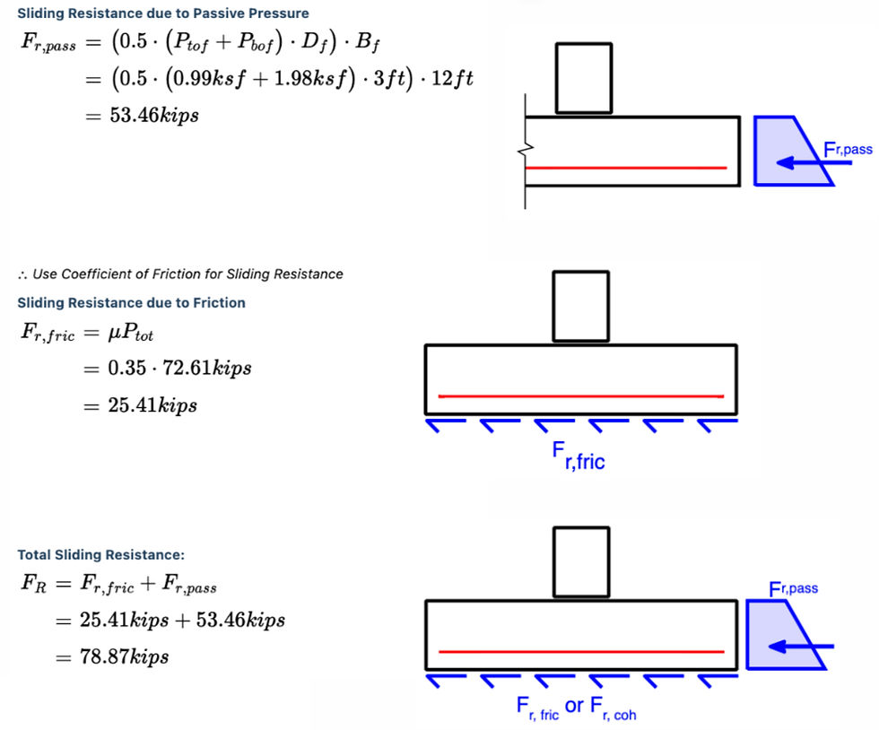
Sliding:
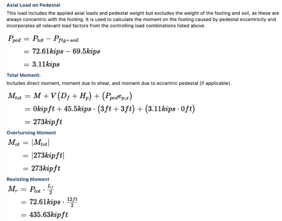
Overturning:
Conclusion:
Braced frames offer a practical and powerful solution for lateral force resistance. With the right design decisions—grounded in code requirements and engineering judgment—you can create systems that are safe, economical, and performance-ready.
Use CalcBook to explore the example problem above or apply the same step-by-step clarity to your own projects. CalcBook helps you save time, reduce errors, and deliver polished, transparent calculations.