
Continuous Column-Beam Moment Connection (AISC 360)
- nick8284
- Jan 23
- 3 min read
Introduction
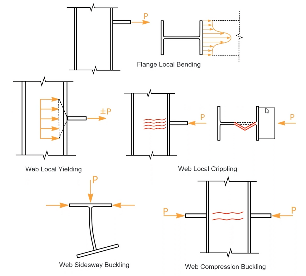
Designing continuous column-beam moment connections is a vital aspect of structural engineering, as these connections must transfer moments from beams on either side of the column safely and efficiently. Following AISC 360 standards, designers need to consider multiple failure mechanisms, such as flange local bending, web local yielding, web local crippling, web sidesway buckling, and web compression buckling. This post will explore these considerations and the specific challenges associated with continuous column-beam moment connections to help engineers develop safe and robust designs.
Factors to Consider
When designing continuous column-beam moment connections, the following factors must be addressed:
Load Direction: Tension vs. Compression
The direction of the concentrated force at the flanges—whether in tension or compression—plays a critical role in determining the governing failure mechanisms. For instance:
• Tension forces require a focus on flange local bending. • Compression forces necessitate checks for web crippling, sidesway buckling, and compression buckling.
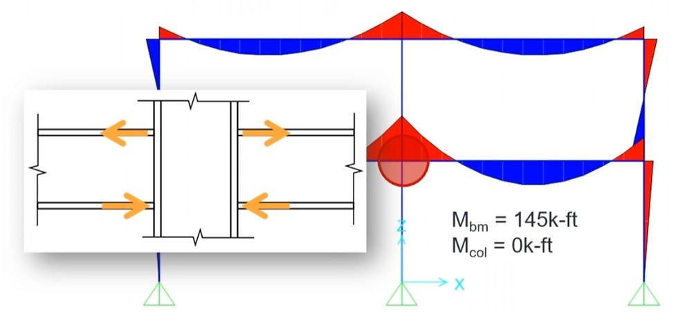
In a continuous column-beam moment connection, both tension and compression forces must be evaluated, as moments applied to the column produce opposing forces in the top and bottom flanges of the connected beam.
Symmetry and Load Sharing
Unlike end connections, where only one side of the column transfers moment, continuous column-beam connections feature beams on both sides. This symmetry often leads to load-sharing effects, which can reduce localized stresses but require careful attention to ensure the column web is not overstressed by combined loads.
Web Compression Buckling
Web compression buckling is particularly critical in continuous connections because both flanges of the column web may experience compression simultaneously. This occurs when the beam moments on either side of the column are of similar magnitude, creating a compression force on both column flanges. Engineers must account for this by checking the capacity of the web to resist such forces.
Connection Type: Full Moment vs. Partial Restraint
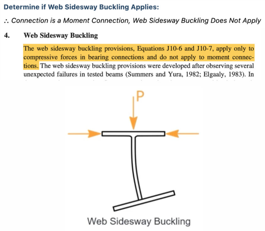
Whether the connection is designed to fully transfer moments or allows for some degree of flexibility significantly affects the design checks. AISC 360 provisions for web sidesway buckling, for example, apply to compressive forces in bearing connections but not to moment connections. For continuous column-beam systems, full moment connections are typically required to maintain structural continuity and stiffness.
Geometry and Shape Factor The geometry of the column and beams—including the flange width, flange thickness, and web depth—has a direct impact on the performance of the connection.
• Shape Factor (Qf): For wide-flange sections, Qf is taken as 1.0. However, for other shapes like HSS, values from AISC Table K1.3 must be used.
• Ensuring that member dimensions and material properties are sufficient for the applied loads is essential for a safe and economical design.
Material Properties
The yield strength, ductility, and toughness of the connected members play a crucial role in ensuring the connection can accommodate applied loads without excessive deformation or failure. Special attention should be given to the ductility demands at the connection to prevent brittle failures, particularly in seismic applications.
Example Problem (Solutions Provided Using CalcBook): Problem Statement:
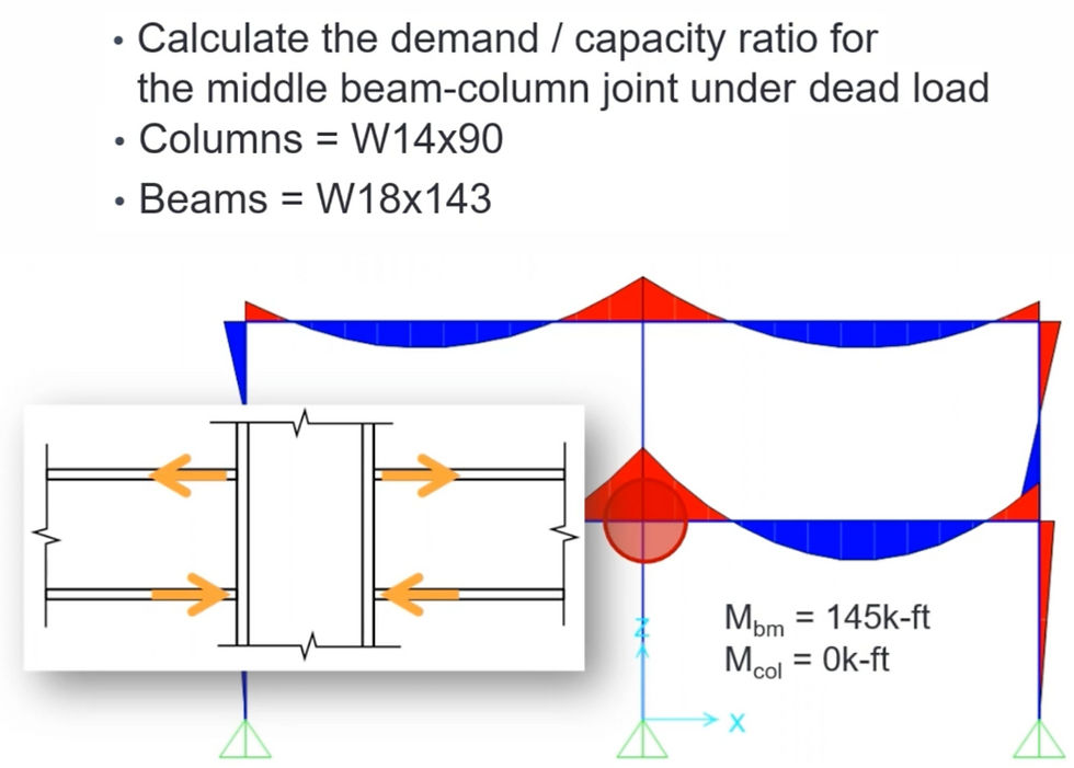
Step 1: Design Inputs

Step 2: Flange Local Bending

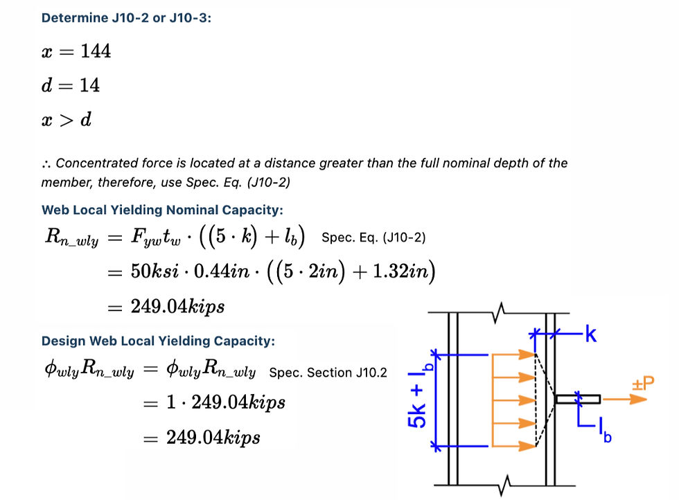
Step 3: Web Local Yielding
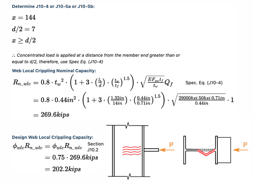
Step 4: Web Local Crippling
Step 5: Web Sidesway Buckling
Step 6: Web Compression Buckling

Step 7: Determine Controlling Demand/Capacity Ratio:

Conclusion:
Continuous column-beam moment connections introduce unique challenges compared to end beam-column connections. Engineers must account for forces acting on both sides of the column, making checks for web compression buckling and load sharing particularly critical. By addressing these considerations and leveraging tools like CalcBook, structural engineers can streamline the design process, ensuring compliance with AISC 360 and delivering efficient, code-compliant connections.